There are several steps to this part. Firstly, a monomer is needed in which the monomer should be stable, highly modifiable and easy to fold. Then, the connection was thought of, we needed a connection that is strong enough, but is modifiable and possibly reversible. Finally, we needed to pair this connection with switches such as aptamers to enable aggregation through ligand binding or other external factors.
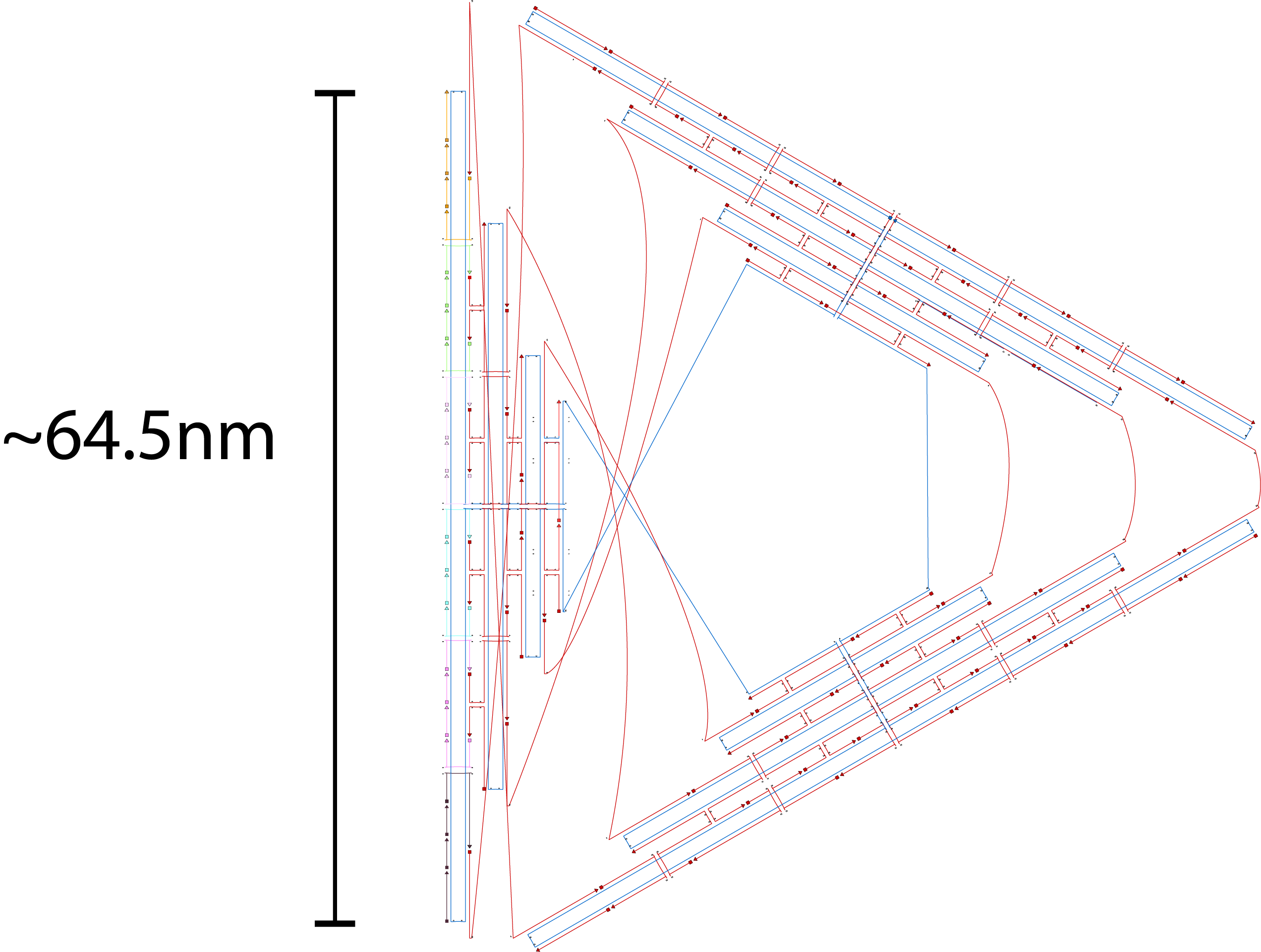
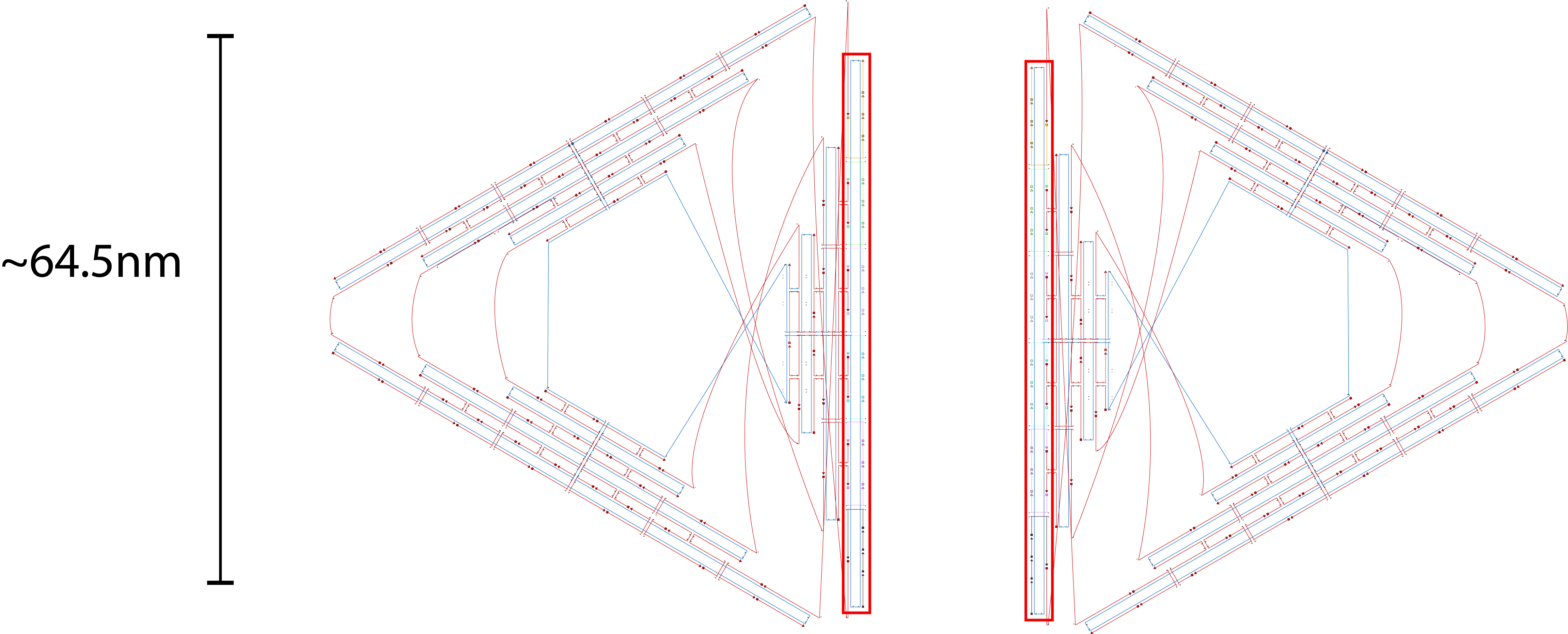
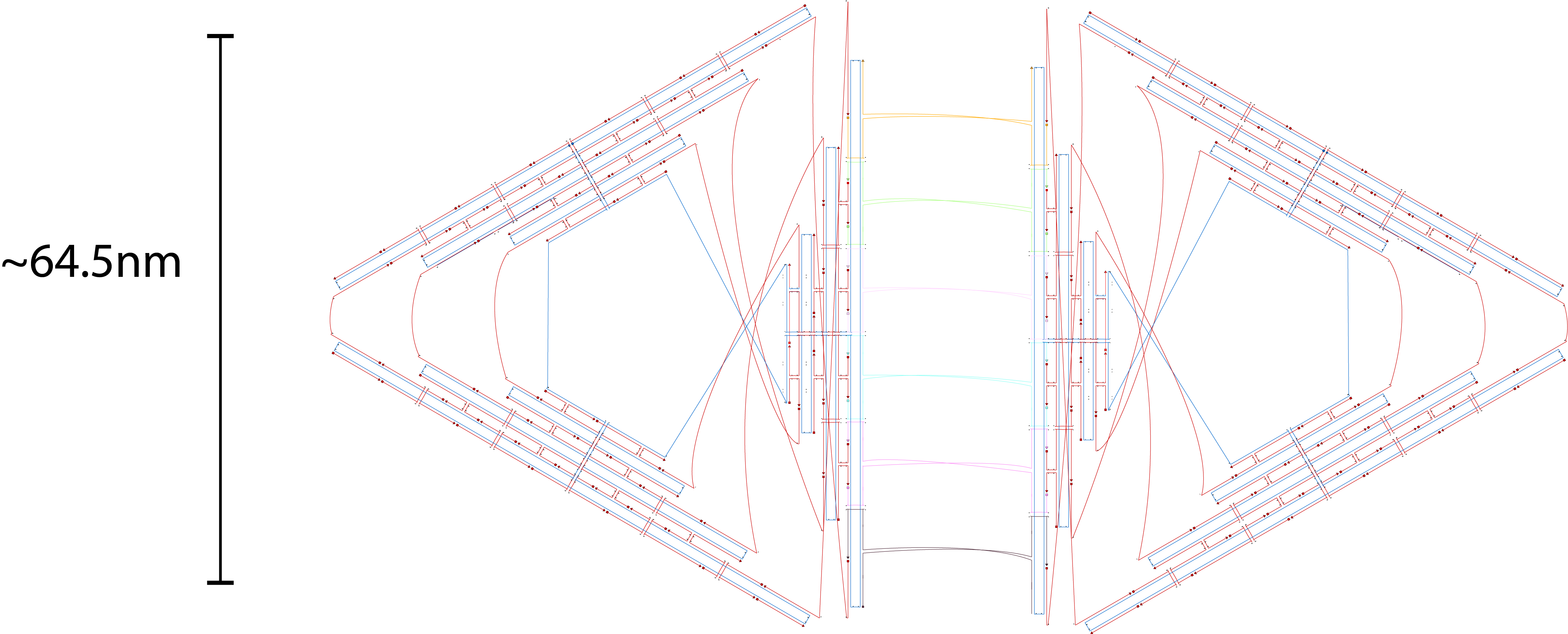
We decided to use the 2D triangle design that has been previously proposed by Rothemund (1) and utilizes the m13mp18 viral ssDNA scaffold. We decided to use this design as this design have been used for other purposes and that this design is rather stable and easy to fold. The design itself is a flat equilateral triangle, however we had to make changes due to funding by tuning down the length of the sides to around 203 bp or 64.5nm in length (refer to fig 1.1). Nevertheless, there is a possibility where the excess scaffold might block and interrupt the process of forming polymers. Furthermore, the triangle has 3 sides of equal length that can help in forming polymers. Finally, modifications for connections can also be attempted by modifying the strands at the sides of the triangles while modifications to add function can be attempted by modifying the staple strands in the center part of the triangle. The monomer has also been simulated by using the webserver CanDo and the result looks stable as seen in fig 1.2.
Fig 1.1. The designed triangle monomer.Fig 1.2. Simulation using CanDo webserver.
Connection design
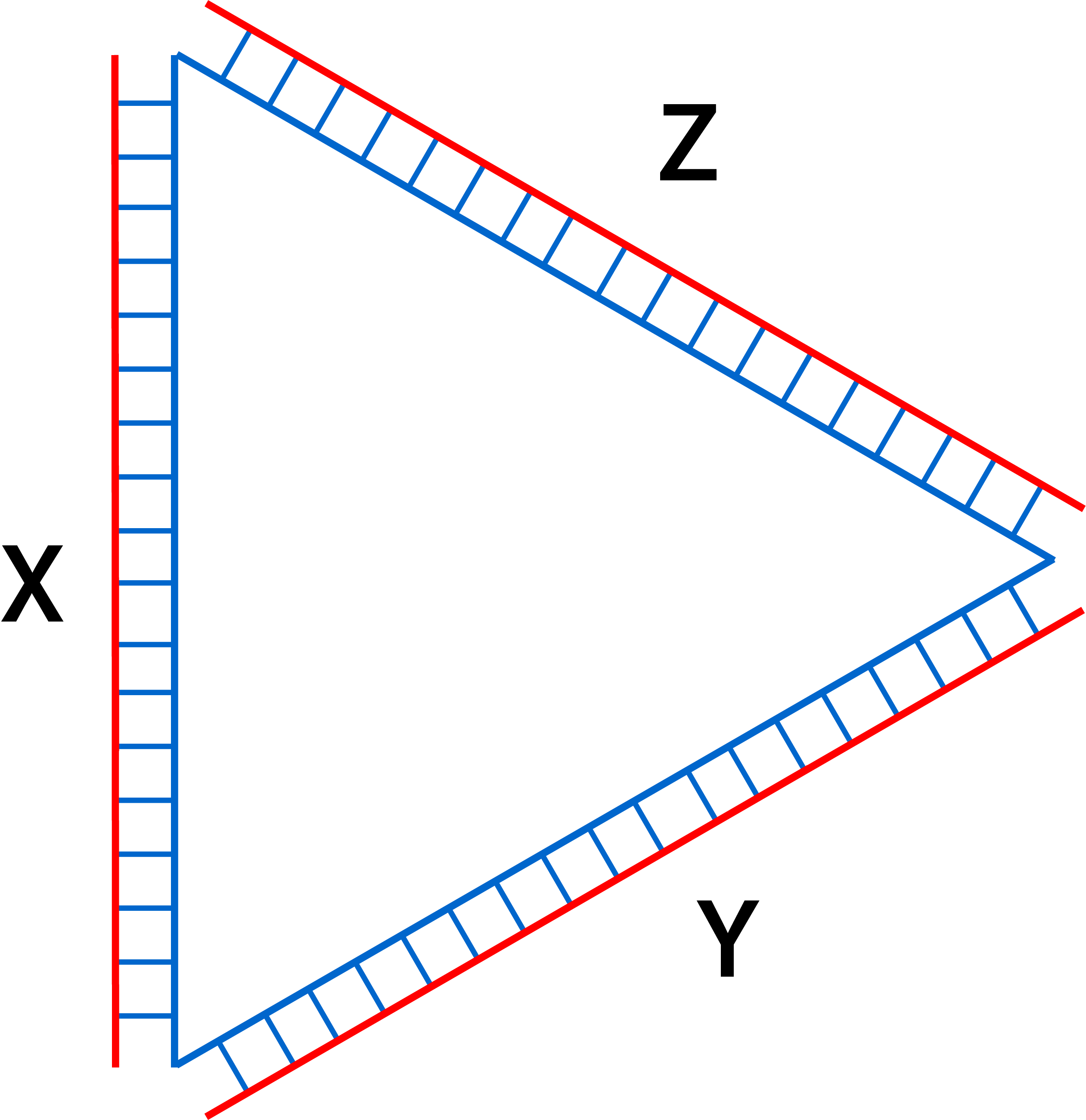
In this section, designs of connection between monomers will be discussed as a mean to swarm the nanostructures. The triangular monomer is simplified by using fig 2.1 to better explain the mechanism between the connections. This simplified monomer only shows parts of the outermost regions consisting of staples (red) and scaffold (blue) as the connection designs utilize similar mechanisms but repeated over the stretch of sides of the triangle. X, Y, and Z show the different sides of the monomers.
Fig 2.1. Simplified version of the monomer designed.
Connection design 1 - through strand replacement
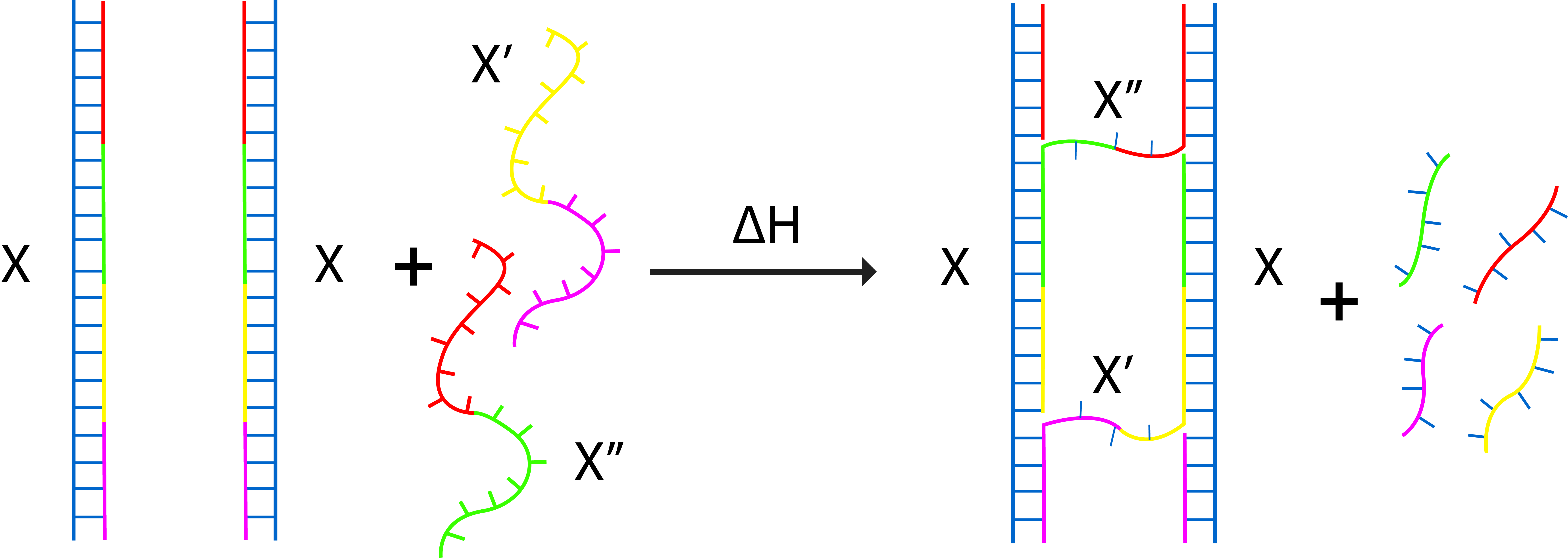
At first, we were looking at a strong but not necessarily the most feasible connection. Therefore, we came up with an idea to replace some staple strands at one side of the monomer with a longer and more thermodynamically stable staple strands. After annealing the previous staple strands, temperature will be raised up and the longer strand will have two binding positions in 2 monomers and connect them as seen in fig 3.1-3.3. This design has a flaw however in which the longer staples might just end up replacing the shorter staples while binding to two sites of a single monomer. The efficiency of connection was observed to be really low and which prompted us to think of different mechanisms. Fig 3.4 shows the simplified drawing of the mechanism.
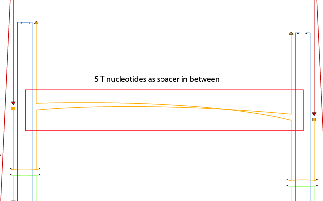
Fig 3.1. The positions where the staples to replace are located.Fig 3.2. The planned replacement of the staples.Fig 3.3. Detailed view of the connection, spacers are put in the staple to prevent the two monomers from getting to close to each other.Fig 3.4. Simplified figure of the connection. Addition of X' and X" plus heat induces the replacement of former staples and connect both monomers.
The caDNAno file for the monomers are unchanged. Only additional strands were added to replace some of the original staple strands.
Connection design 2 – through complementary protruding strands
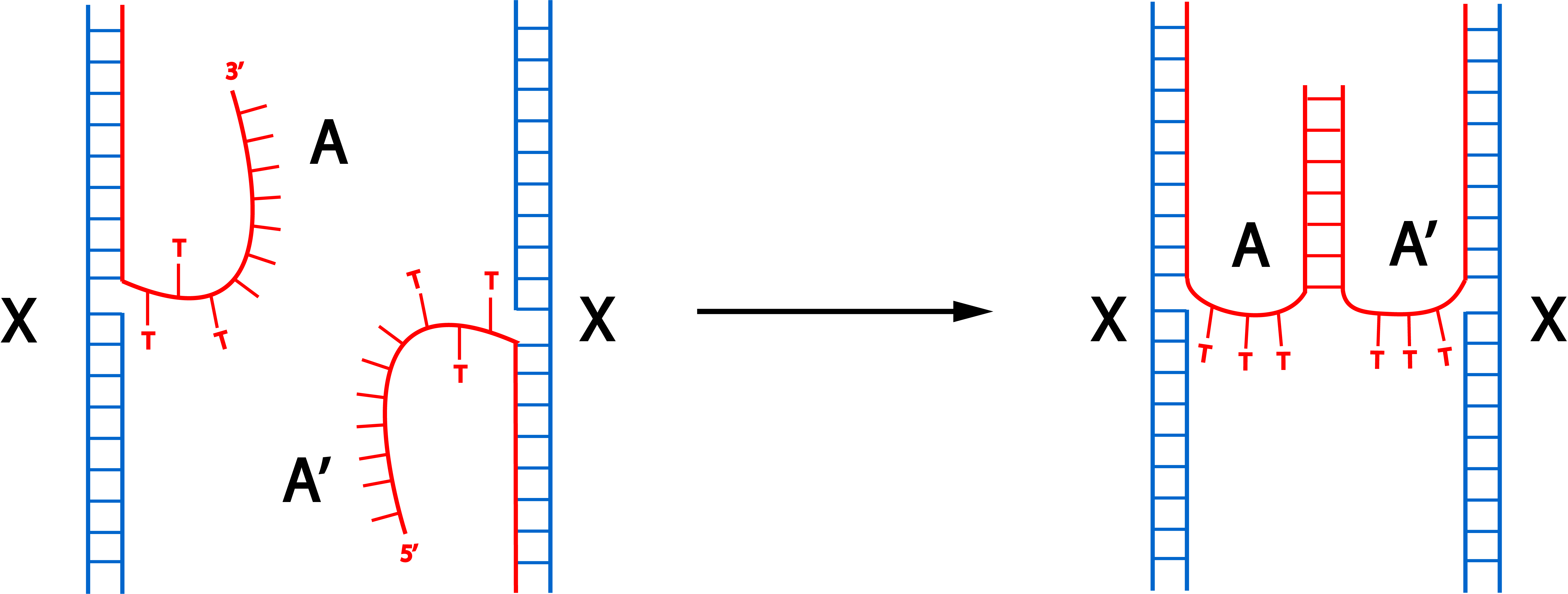
As the first connection design proved to be ineffective, we thought of another way to connect the monomers. This connection design involves protruding staples that are complementary to each other. The annealing process to fold the monomers have to be performed separately to create 2 similar monomers only distinct at the side where the staples are modified.
Fig 3.1 Proposed connection through hybridization of orthogonal protruding strands. A and A’ shows complementary protruding strands that can hybridize. T spacers are put between the sequence of the staples and the orthogonal sequences.
The protruding strands utilize orthogonal ssDNA (2) that have a low chance of producing secondary structures as tested by using Nupack (3) accessible from www.nupack.org . The results of hybridization simulations are shown in Fig 3.2 respectively. The strands 73-75XYT shows the staples that are used for hybridization in which X denotes A or A’ (denoted by A and B) of fig 3.1 and Y denotes the number of thymine spacer. These results show that the orthogonal strands will hybridize with the strands of the other monomer with high efficiency.
Fig 3.2. Simulation through Nupack under the condition 1 μM of ssDNA, 25°C, 0.1M NaCl and 0.01M MgCl2 for strands with 3 T spacers.Fig 3.3. Simulation through Nupack under the condition 1 μM of ssDNA, 25°C, 0.1M NaCl and 0.01M MgCl2 for strands with 8 T spacers.
The caDNAno file for the monomers was changed as the staples were adjusted to accomodate for the complementary protruding strands. Furthermore, additional strands were added to replace some of the original staple strands. The staples for the monomer are the same, however staples 73-90 of the original design are to be replaced by staples specified in the following spreadsheet.
Connection design 3 - through bridged protruding strands
This connection mechanism also employs protruding strands that protrude from the triangular monomers but cannot hybridize with each other. Hybridization will occur when another longer strand that complements both strands (shown as F) gets introduced into the solution as depicted in fig 4.1.
Fig 4.1. Hybridization of introduced strand F and orthogonal protruding strands A and B induces connection between the sides of the monomers.
This mechanism adds flexibility to the design as it is possible to elongate this connector strand (bridge) and incites deactivation through swarming by using DNA fuel strands (4) to release the bridge as seen in fig 4.2.
Fig 4.2. In this figure, addition of longer strand F incites formation of connection between the sides of the monomers. With the introduction of F’, the strand F gets released and thus the connection is also broken.
In the design of the bridge, we found that there are parts with 4 or more repeated guanine bases with chances of forming guanine quadruplex (5) which is a stable secondary structure which makes it harder both to synthesize and assist in connecting the monomers. Therefore, we replaced some of the guanine bases with adenosine as adenosine can wobble-pair with cytosine (6).
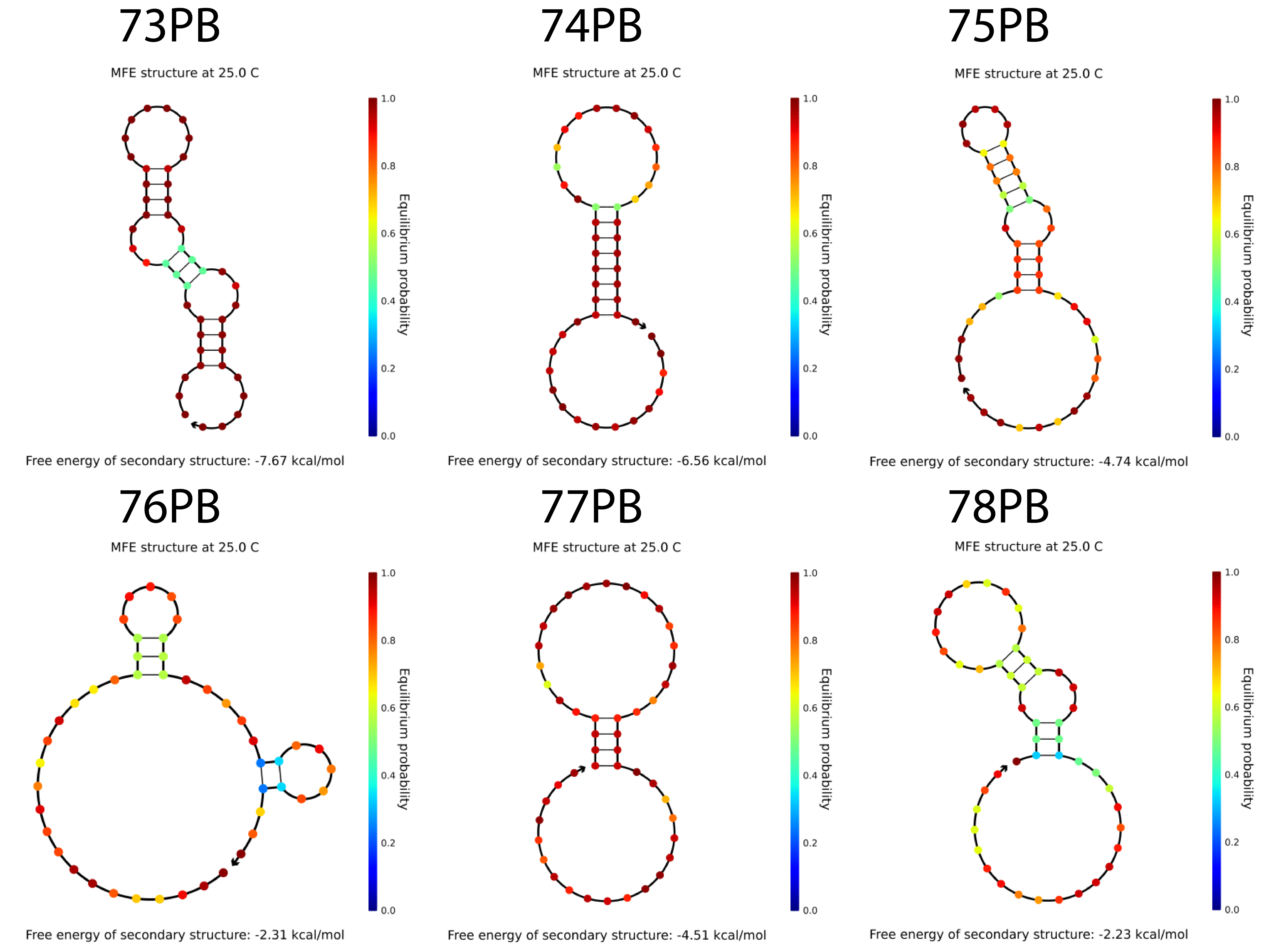
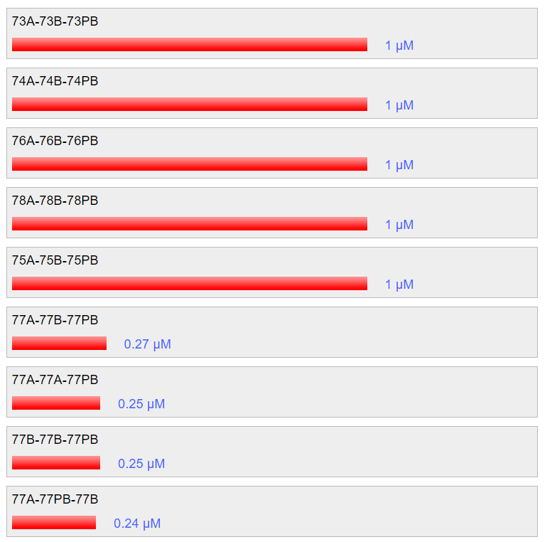
The bridges have been tested in nupack and was able to form rather stable secondary structures which means that it might have difficulty in connecting the protruding strands. Nevertheless, hybridization between the bridge strands and the protruding strands have also been tested to 100% form hybridized structure involving the 3 complexes when the condition is 25°C, 0.1M NaCl and 0.01M MgCl2.
The bridges have been tested in nupack and was able to form rather stable secondary structures (refer to fig 4.3) which means that it might have difficulty in connecting the protruding strands. Nevertheless, hybridization between the bridge strands and the protruding strands have also been tested to form hybridized structures involving the 3 complexes when the condition is 25°C, 0.1M NaCl and 0.01M MgCl2 at 100% except for sequence 77. This should not be a problem as the other 5 combinations should hybridize without any problem.
Fig 4.3. The predicted secondary structure of the bridges. Fig 4.4. The probability of hybridization when 1 μM of each strands are present.
The caDNAno file for the monomers has not changed. Only additional strands were added to replace some of the original staple strands along with the bridge.
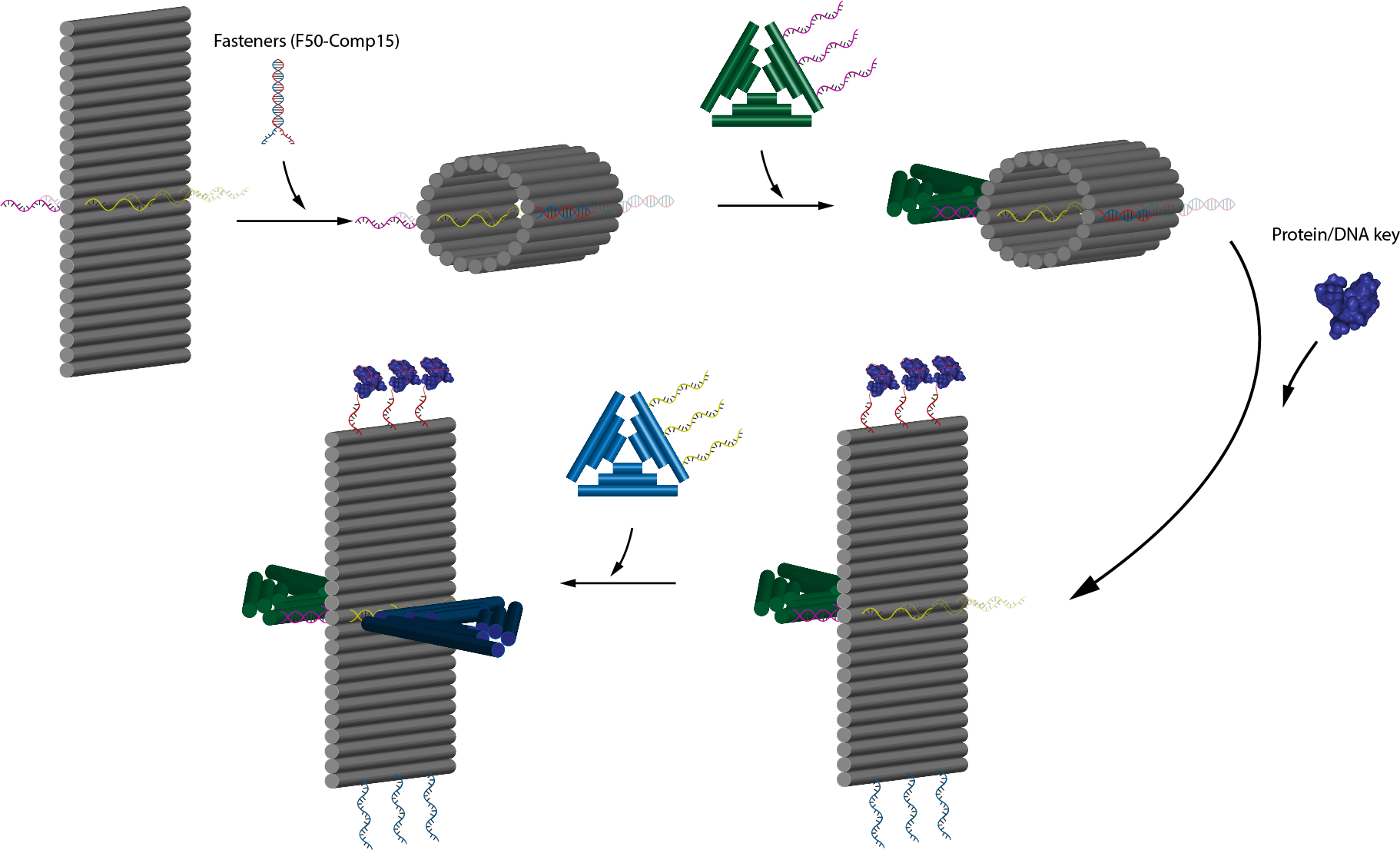
Trigger mechanism - Aptamer mediated lock
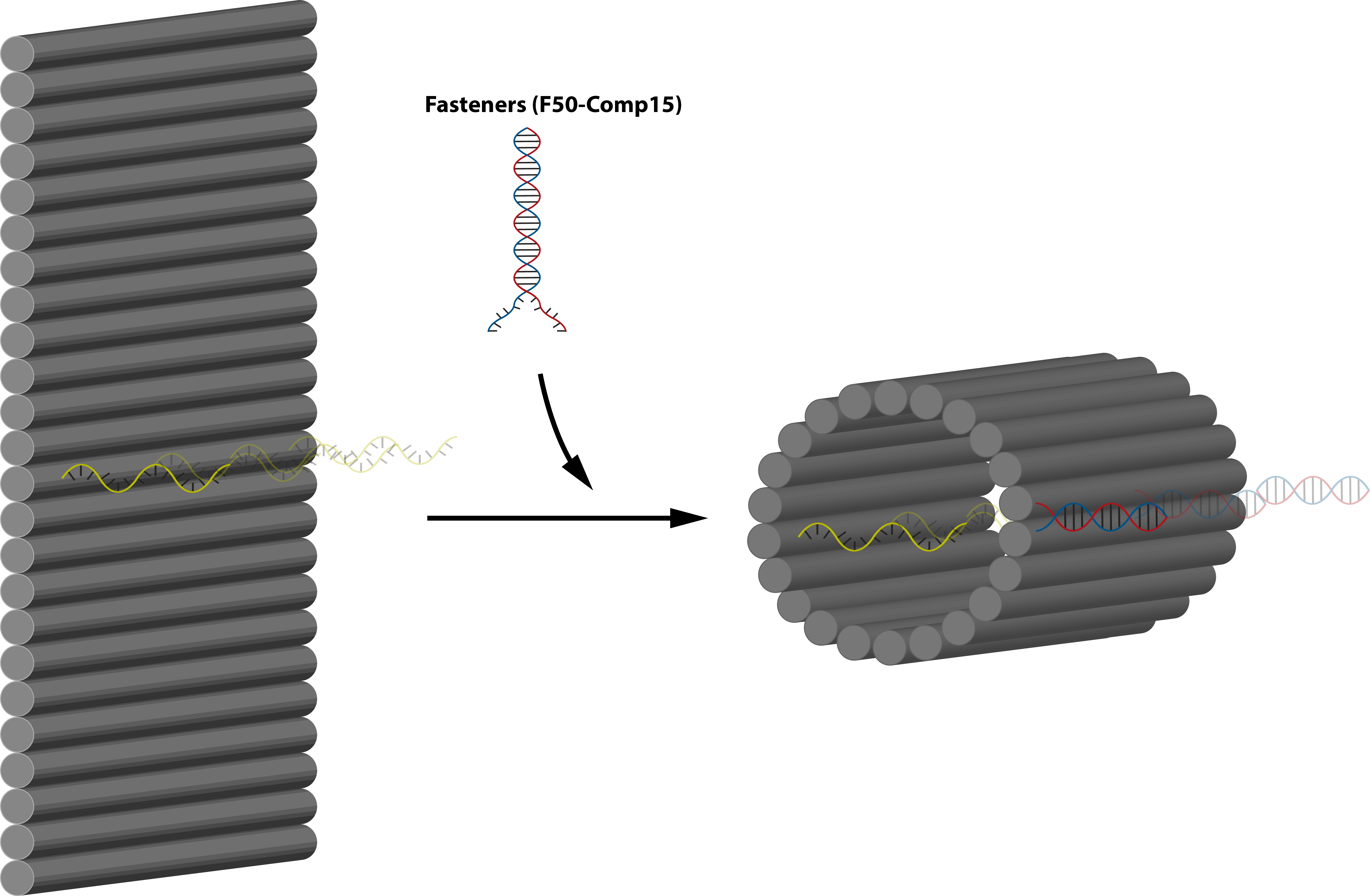
In this part, we are planning to utilize the design by Li et al. (7) as well as incorporating connection design 2. By using this, we will be able to control whether the protruding orthogonal strands will be exposed or not through ligand binding. In principle, the flat sheet will have side fasteners that can close it into tube and when ligand binding is initiated it will open, exposing the orthogonal strand located perpendicular to the sheet and inside the tube (connection design 2). This sheet will then serve as an adapter between two monomers. The flow of the mechanism is expalined on figure 5.1, is further explained on fig 5.3 and the target activation of the module is on fig 5.4. Nupack simulation shows that the fasteners are able to fasten the structure at a high efficiency as shown on figure 5.5.
The adapter uses the m13mp15 scaffold strand and the staple strands are as described in the following spreadsheet:
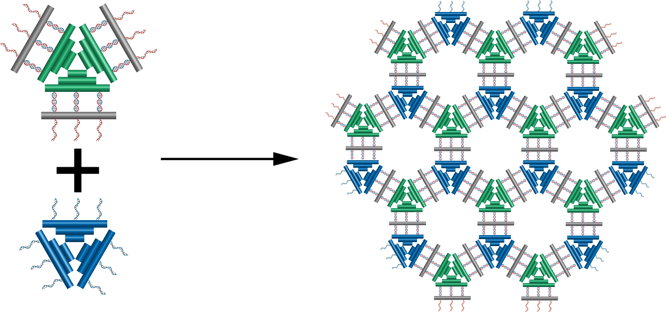
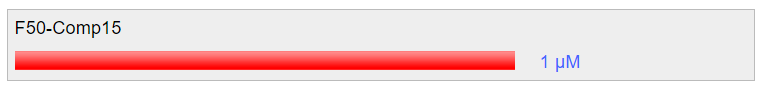
Fig 5.1. Overall mechanism of the trigger design.Fig 5.2. 3D concept image showing how 2 different type of monomers, one with the trigger mechanism and one without can form polymers. Fig 5.3. 3D concept image showing the addition of fasteners to lock the adapter and concealing the protruding strand on the face of the sheet.Fig 5.4. Activation of the module through nucleolin binding.Fig 5.5. Simulation through Nupack under the condition 1 μM of ssDNA, 25°C, 0.1M NaCl and 0.01M MgCl2 for the aptamer and the complementary strand.
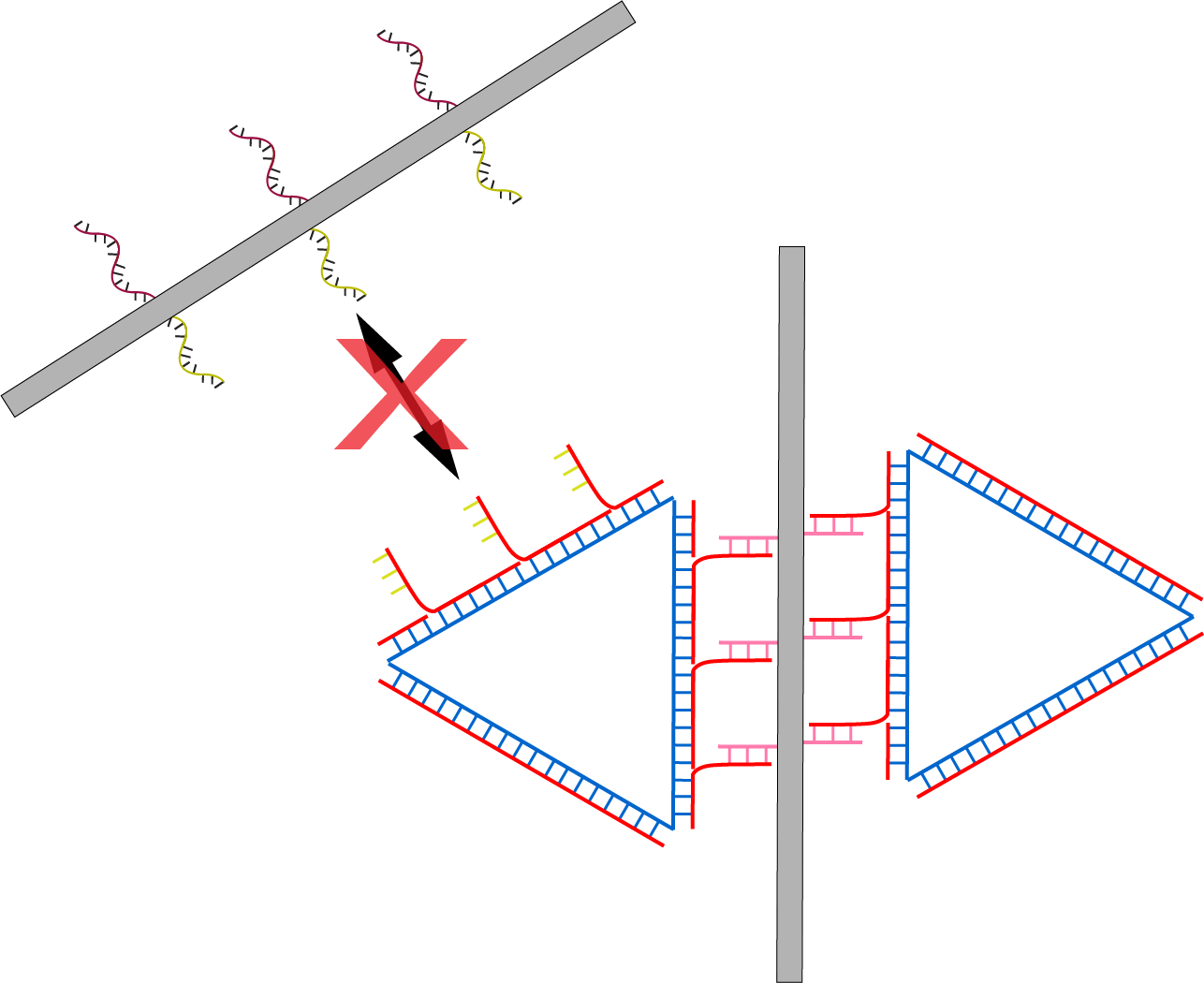
The problem with this design as shown in fig 5.6 is that if the sheet length is longer than the triangle side length, it will not be possible to form polymers due to steric hindrance by the sheet that hinders the attachment of successive monomers to the initiating monomer. This, however, can be solved by either elongating the sides of the triangular monomer or by redesigning the tube to make it shorter.
Fig 5.6. Limitation to the mechanism due to smaller monomer.
To add the protruding strands to the design, we firstly edited strands number 55, 79, 103, 127, 151, and 175 at their 5’ ends to resemble robot B from connection design 2. The orientation was also put on top, which means that after the addition of fasteners to close the tube, the protruding strands are expected to be hidden well inside the tube, hidden from the protruding complementary strands of the monomers.
The sequences for the protruding strands are available in the following spreadsheet:
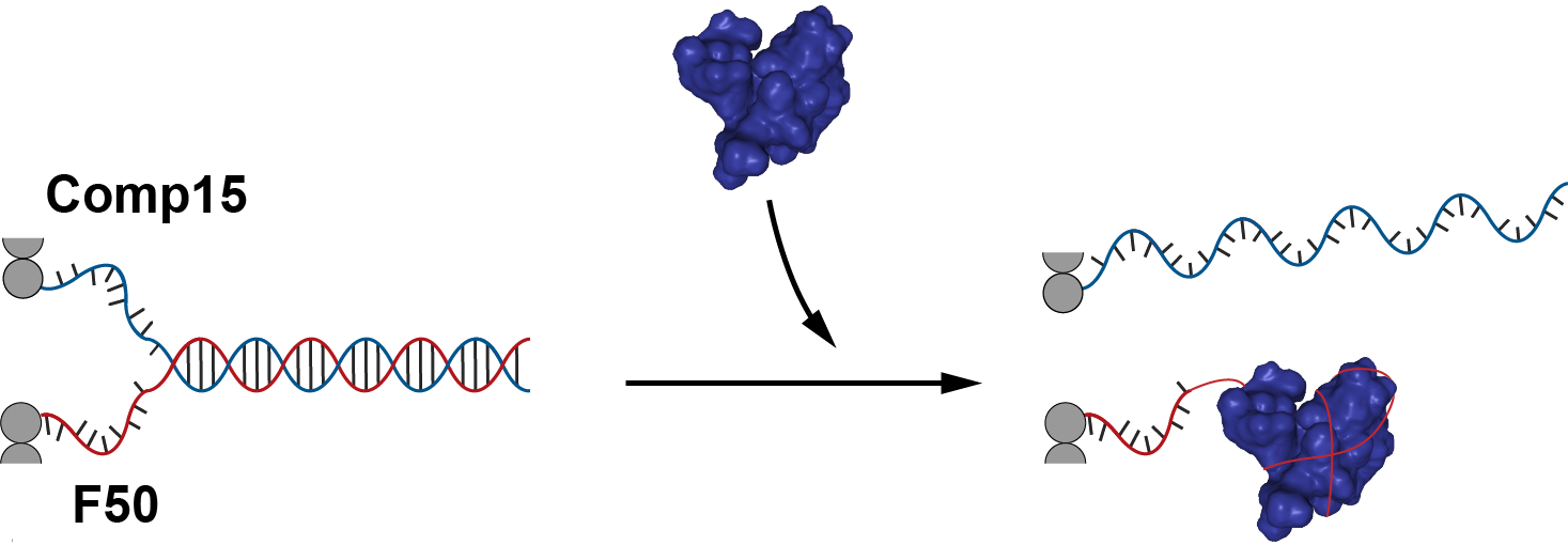
In this case, the addition of nucleolin will open the tube by releasing the fastener and thus exposing the protruding strands. This enables hybridization with protruding strands of robot A. Therefore, if we are able to connect the sheet onto another robot (remember that protruding strands from robot B were used in the sheet), we can control the connection of 2 different robots through this adapter.
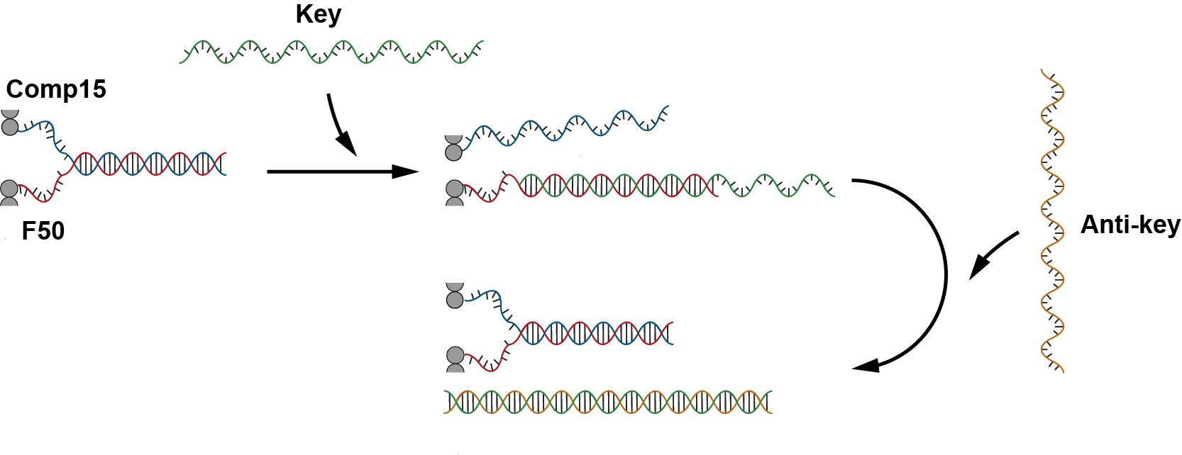
Before using nucleolin however, we try unlocking and relocking the structure through thermodynamically favorable strand (key and anti-key) additions. Firstly, after the addition of the fasteners, the sheet will close into a tube. Then, after the addition of the key, the cylinder will open to form sheet and the protruding strands will be exposed and free to hybridize with monomers. Addition of anti-key will then reverse the process and close the sheet into tube again. Details to this mechanism is shown in fig 5.7.
Fig 5.7. Triggering mechanism by using ssDNA (key) and release by anti-key.
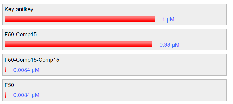
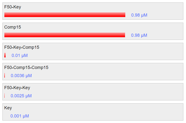
Nupack simulation at 25C shows that the key will be able to hybridize with the strands of the fastener, unlocking the structure similar to unlocking by nucleolin to a high efficiency: around 98% in the simulation. Furthermore, the addition of anti-key has been shown to recover the previous structure efficiently, also at around 98% according to the simulation. The results are shown in fig. 5.8 and fig 5.9 respectively.
Fig 5.8. Simulation through Nupack under the condition 1 μM of ssDNA, 25°C, 0.1M NaCl and 0.01M MgCl2 showing unlocking using key strand.Fig 5.9. Simulation through Nupack under the condition 1 μM of ssDNA, 25°C, 0.1M NaCl and 0.01M MgCl2 to release the key and restore the tube formation.
The sequences of the key and anti-key are available in the following spreadsheet:
References
Rothemund,P.W.K. (2006) Folding DNA to create nanoscale shapes and patterns. Nature, 440, 297–302.
Kitajima,T., Takinoue,M., Shohda,K. and Suyama,A. (2008) Design of Code Words for DNA Computers and Nanostructures with Consideration of Hybridization Kinetics. In Garzon,M.H., Yan,H. (eds), DNA Computing. Springer Berlin Heidelberg, Berlin, Heidelberg, Vol. 4848, pp. 119–129.
Zadeh,J.N., Steenberg,C.D., Bois,J.S., Wolfe,B.R., Pierce,M.B., Khan,A.R., Dirks,R.M. and Pierce,N.A. (2011) NUPACK: Analysis and design of nucleic acid systems. Journal of Computational Chemistry, 32, 170–173.
Yurke,B., Turberfield,A.J., Mills,A.P., Simmel,F.C. and Neumann,J.L. (2000) A DNA-fuelled molecular machine made of DNA. Nature, 406, 605–608.
Burge,S., Parkinson,G.N., Hazel,P., Todd,A.K. and Neidle,S. (2006) Quadruplex DNA: sequence, topology and structure. Nucleic Acids Research, 34, 5402–5415.
Leontis,N.B., Stombaugh,J. and Westhof,E. (2002) The non-Watson-Crick base pairs and their associated isostericity matrices. Nucleic Acids Res., 30, 3497–3531.
Li,S., Jiang,Q., Liu,S., Zhang,Y., Tian,Y., Song,C., Wang,J., Zou,Y., Anderson,G.J., Han,J.-Y., et al. (2018) A DNA nanorobot functions as a cancer therapeutic in response to a molecular trigger in vivo. Nature Biotechnology, 36, 258–264.